 INTEGRAL Spacecraft, Launcher and Orbit
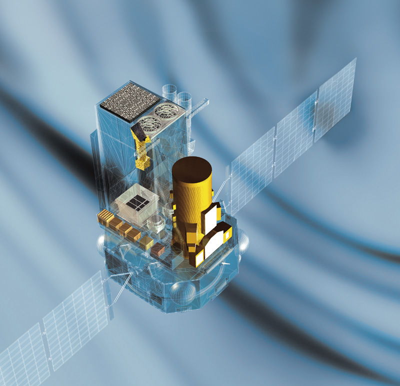
Spacecraft

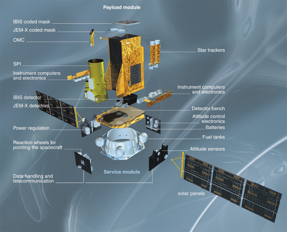
The spacecraft consists of a service module (bus) containing all spacecraft
subsystems and a payload module containing the scientific instruments.The
service module will be identical for the two ESA scientific missions, Integral
and XMM. The simplicity of the interface between service and payload module
is a major design driver. The electrical interface is reduced to a power
and data handling bus. The modular approach has been conceived to allow
for a parallel development, assembly, integration and test of service and
payload module, respectively.
The spacecraft has been built under ESA contract by a large
industrial consortium, led by Alena Spazio (I) as prime contractor.
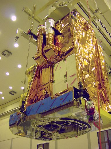
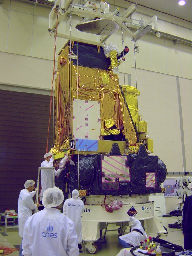
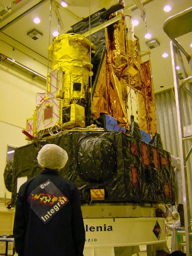
Pictures from the INTEGRAL spacecraft
Pictures from the spacecraft during structural and thermal testing
(STM) in ESTEC (June/July 1998) can be found here:
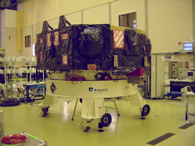
Pictures of the payload module during STM testing:
Fig. 1,
Fig.
2,
Fig. 3,
Fig.
4.
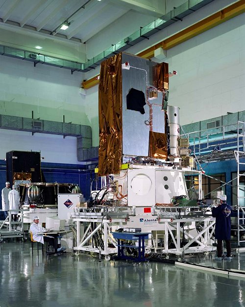
The INTEGRAL Electrical Model (EM) during testing at Alenia/Italy
(Summer 1999)
is shown here.
First image from the Flight model can be found here.
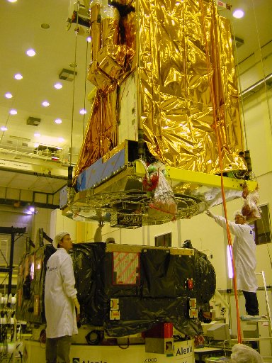
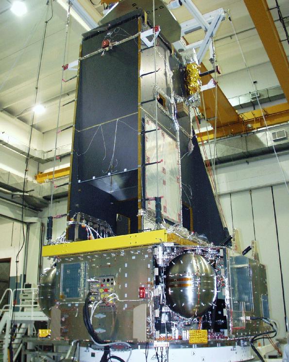
Sequence of pictures showing the mating of the INTEGRAL FM payload
module and service module in ESTEC (August 2001)
Fig. 1,
Fig.
2,
Fig.
3,
Fig.
4,
Fig.
5,
Fig.
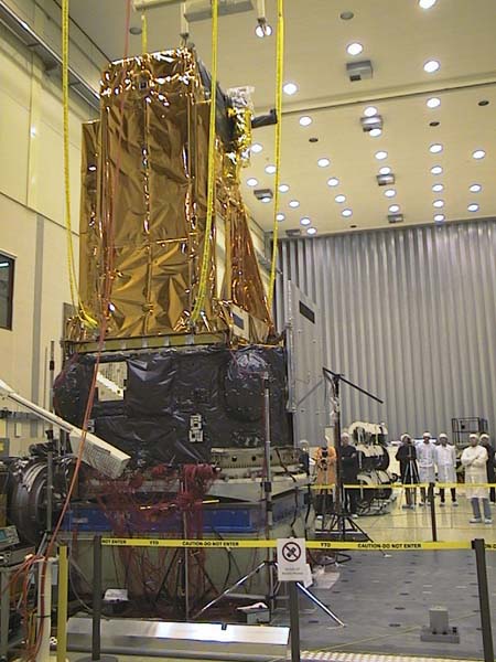
The spacecraft on the "shaker"
just prior to vibration test on z-axis (September 2001).
Link to
video
showing: PLM/SVM mating, Transport to shaker, Vibration test on z-axis
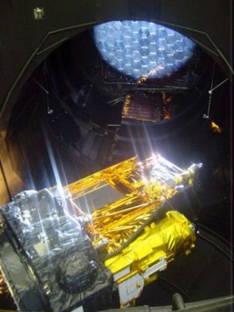
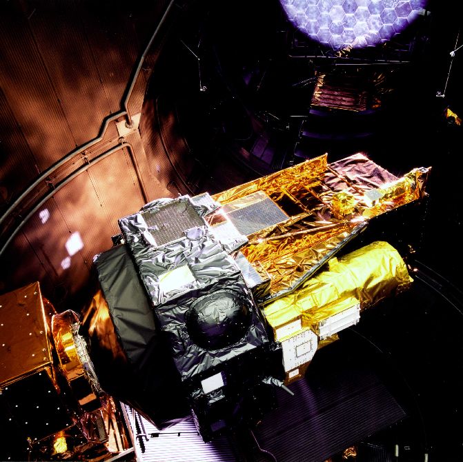
The INTEGRAL Flight Model Spacecraft inside
the ESTEC Large Solar Simulator (May 2002)
INTEGRAL spacecraft with instrument
details.
Launcher & Orbit
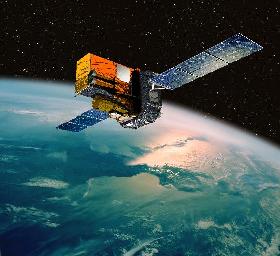
Integral (with a total launch mass of about 4 t) will be launched in
2002 into a geosynchronous highly eccentric orbit
with high perigee in order to provide long periods of uninterrupted observation
with nearly constant background and away from trapped radiation (electron
and proton radiation belts).
INTEGRAL will be launched with a Russian PROTON
launcher from Baikonur/Kazachstan.
The initial orbital parameters are:
-
72-hour orbit with an inclination of 51.6 degrees, a height of perigee
of 9 000 km and a height of apogee of 155 000 km
Owing to background radiation effects in the high-energy detectors,
scientific observations will be carried out while the satellite is above
a nominal altitude of 40 000 km. This means, that ~90 %
of the time spent in the orbit provided by PROTON can be used for (real-time,
85.8 kbps) scientific observations. An on-board particle radiation monitor
allows to assess the radiation environment local to the spacecraft. In
case of low background environment, observations below 40.000 km altitude
should be possible.
More details on the launcher technical performance can be found here.
The Real-Time orbital elements and the current position of the satellite
can be found here.
(Courtesy of Heavens-Above GmbH)
Spacecraft Pointing and Dithering
The spacecraft utilises fixed solar arrays, and therefore pointing to
any point on the sky at any time is constrained by thermal (and power)
reasons: the difference between the solar array normal vector and the sun
vector can be up to 40 deg during the first two years of operations (during
eclipse seasons: up to 30 deg) and up to 30 deg during the extended mission
phase (from end of second year of operations up to 5 years). This viewing
constraint implies that the spacecraft (instrument line of sight) can not
point to sources which are closer than 50 deg (60 deg) to the sun
and to the anti-sun during nominal lifetime (eclipse seasons and extended
lifetime).
During the first two years of the mission the spacecraft can point
to 64% of the celestial sphere at any point in time (50 % of the celestial
sphere for the extended mission phase).
In order to suppress systematic effects on spatial and temporal background
variations in the spectrometer (SPI) detectors, a controlled and systematic
spacecraft dithering ("raster-scan")
manouevre is required. This manoeuvre shall consist of several off-pointings
of the spacecraft pointing axis from the target in steps of 2 deg. Two
different pointing patterns (modes) are foreseen as operational baseline:
mode 1 consists of a hexagonal pattern around the nominal target location
(1 source on-axis pointing, 6 off-source pointings, each 2 deg apart);
mode 2 consists of a square pattern around the nominal target location
(1 source on-axis pointing, 24 off-source pointings, each 2 deg apart).
Mode 1 will be used for a single known point source, mode 2 for multiple
point sources in the FOV, sources with unknown locations, and extended
diffuse emission which can also be observed through combination ("mosaic")
of mode 2 patterns. The integration time for each pointing on the raster
shall be 2200 sec. The spacecraft will continuously follow one dithering
pattern throughout one observation. If scientific requirements (i.e. observation
proposals) exist to observe sources for long uninterrupted periods of time
using all 4 instruments (e.g. for studies of time variability or QPO's)
then the dithering modes can be switched off.